Stylized Surface Shader
When you create a material, you’ll choose a shader. By default, Unity has the standard shader picked up. Once installed, all Flat Kit material shaders are located under the Flat Kit sub-menu of the Shader drop-down menu. Please choose the one that would work for your current task. Below is the description of all the shaders.
Our shaders expose shading properties as material features. If a feature toggle is not activated on any materials in the build scenes, the portion of shader code for that feature is not included in the build. Because of the fact that these shaders are designed for a stylized look as opposed to photorealistic, metallicness and translucency features are not supported. The support for PBR (Physically-Based Rendering) in Flat Kit means that indirect sources of light (e.g. skybox) influence the colors of the material, unless you turn this feature off.
‘Stylized Surface’ Shader
This is a versatile lit shader to be used on rigid object materials. To use it on a material select the shader FlatKit/Stylized Surface or FlatKit/Stylized Surface Cutout (Built-In RP only). This is your main go-to shader. It works for the vast majority of cases.
Stylized Surface shader consists of the following main building blocks:
- Color
- Cel Shading mode (None, Single [Cel], Steps, Gradient)
- Extra Cel layer
- Specular
- Rim
- Height Gradient
- Outline
The additional parameters are:
- Advanced Lighting
- Unity Built-in Shadows
- Textures (Albedo, Normal, Emission)
- Rendering Options
Each combination of the features above, used in your project results in generating a shader variant during the build process. To limit the build time and the resulting binary size be careful not to add un-useful feature combinations. On the other hand, this mechanism makes sure that only the used features are included in the build. More information on shader variants: https://docs.unity3d.com/Manual/SL-MultipleProgramVariants.html
‘Stylized Surface’ shader collapsed view. Single mode. Simple use case
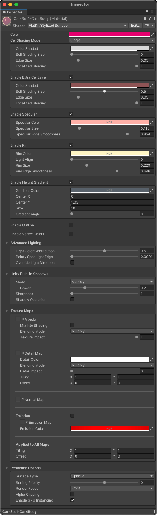
‘Stylized Surface’ shader in expanded view. Single mode. More complex use case with more options engaged, but still, uses only Single mode
The Main Parameters of the Shader
Color
This would be the color of your mesh (applicable to most cases, though you can make the shader’s other parameters override or mask this main color, if you wish).
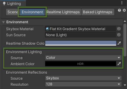
NOTE. The flatness and actual representation of colors on the scene depend on the source of lighting in the scene. In the Lighting panel ▶︎ Environment tab, if you select Color as the source of lighting and set Ambient Color to black, the colors you choose inside the materials will look identically to those represented on the scene.
Cel Shading Mode
This is where you choose the style (mode) of your shading, the color of the shading and other parameters unique to the modes.
-
None. Use this to achieve a simple flat look with the color picked in the Color parameter above. If you’d like, you can still make the visuals look complex by adding Extra Cel Layer, Specular, Rim, Outline etc (all described below), while being in ‘None’ Cel Shading Mode.

You can select None mode and enable Extra Cel Layer (described below) to get a similar effect to Single mode.
-
Single. This mode provides you with one cel layer of chosen color.

- Color Shaded is the color of the cel. It is not an HDR parameter.
- Self Shading Size is the size of the cel. Larger values mean larger size of the shadow.
- Shadow Edge Size controls the sharpness of the cel. The lower the value — the sharper the cel. The higher the value — the more blurry is the shadow.
- Localized Shading is basically how condensed the shadow is. Higher values represent sharper cel.
-
Steps. Basically, you choose the shading color and number of steps to blend from main Color into the color you pick up in Steps mode.

- Color Shaded is the color of the cel you’d like to blend to. It is not an HDR parameter.
- Number of Steps is the number of steps to blend from main Color into the color you pick up in Color Shaded parameter.
-
Save Ramp Texture is a button to save the texture of the gradient. This is useful if you’d like to use the same gradient in other shaders. The texture will appear red in the editor. This is because internally we use the R8 texture format for efficiency.
After you click the Save Ramp Texture button, you’ll see the prompt to choose where in the project folder you’d like the texture to be saved. You can use it in other materials and shaders.
The texture will appear in the Cel steps parameter.
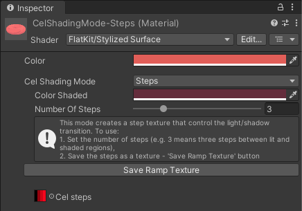
Steps shading mode of Stylized Surface shader
-
Curve. The gradient, interpolated transition from main Color to Color shaded.

In order to get Steps and Curve modes to work — as soon as you have a number of steps (Steps mode) or curve shape (Curve mode) chosen — the shader will ask you to save its utility ramp texture somewhere on the disk. It will write the transition onto it. The texture will appear red in the editor. This is because internally we use the R8 texture format for efficiency.
- Color Shaded is the color of the cel you’d like to blend to. It is not an HDR parameter.
- Save Ramp Texture is a button to save the texture of the gradient. This is useful if you’d like to use the same gradient in other shaders. The texture will appear red in the editor. This is because internally we use the R8 texture format for efficiency.
-
Shading curve is the curve of the gradient. You can edit it by clicking on the curve and dragging the points. You can also add new points by clicking on the curve. You can remove points by clicking on them and pressing the Delete button on your keyboard.
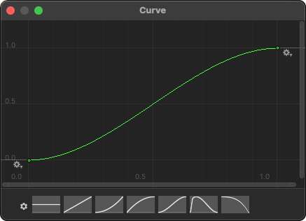
Curve Editor appears when you click on the curve
After you click the Save Ramp Texture button, you’ll see the prompt to choose where in the project folder you’d like the texture to be saved. You can use it in other materials and shaders.
The texture will appear in the Ramp parameter.
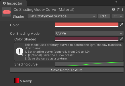
Curve shading mode of Stylized Surface shader
 Please note that the models you are working with can be either flat-shaded or smooth-shaded or in a 3D editor (e.g., here is the reference in Blender). If you have a model with smooth-shaded normals, the cel shading will be smooth as well in Unity. If you have a model with flat shading, the cel shading will appear blocky. But you can adjust smoothing in Unity as well — in the Import Settings of the model → Normals section.
Extra Cel Layer
This is like another instance of Single mode of Cel Shading Mode. Works independently from the ‘Single’ Cel Shading Mode. This means, you can set Cel Shading Mode to None (flat), and add an Extra Cel Layer. The result will be the same as if you would have used the Single mode. Or choose the ‘Single’ Cel Shading Mode and make Extra Cel Layer almost identical to it, giving an Extra Cel Layer a darker color, and making it smaller. This would result in stepping, similar to Steps Mode with 1 step. Classic toon.
Specular
You can make a, well, specular (glare) with this parameter. Also it can be used as another layer of shadow.
- Specular Color picks up the color of your glare, the parameter works in HDR.
- Specular Size determines how big the specular is. Higher values mean bigger specular.
- Specular Edge Smoothness — moving slider to the left decreases blurriness and makes specular sharper.
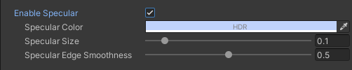
Specular. Inspector interface
Rim
Rim was designed as one of the ways to make a specific effect of a color ‘wrapping’ from behind the object (a fresnel effect, in a nutshell). In some cases it can remind an outline effect.
Please, note that the object has to have curvature. A completely flat object wil be completely included in the rim or completely not included, depending on the angle of view.
- Rim Color selects the color of the parameter. It works in HDR.
- Light Align parameter rotates the rim.
- Rim Size controls how big the Rim is. Very high values can serve you as an unlit effect.
- Rim Edge Smoothness — moving slider to the left sharpens the Rim, to the right — makes Rim blurry.
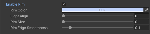
Rim. Inspector interface
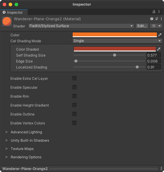
You can think of Rim as some kind of inner shadow and/or as inner glow, if used on smoothened curvy models. In one of the Fruit Vase demo scenes, there is an example of extensive use of Rim as an outline. On Blueprint Grid demo scene Rim is used as a smooth inner glow. This parameter can be used creatively, for example, to substitute Curve mode or Extra Cel parameter. Just reminding you that the name like ‘Rim’, ‘Specular’ etc should not be perceived literally, they can do more than that. In the screenshot below, with the help of Suzanne the Blender Monkey, we tried to show a few instances of Stylized Surface shader with None mode selected (meaning no straightforward shadows are applied), using orange color, and only Rim parameter enabled. The results are variations of Rim section only. As you see, the Rim alone is quite a creative tool. Imagine adding some creative Specular and Height Gradient…
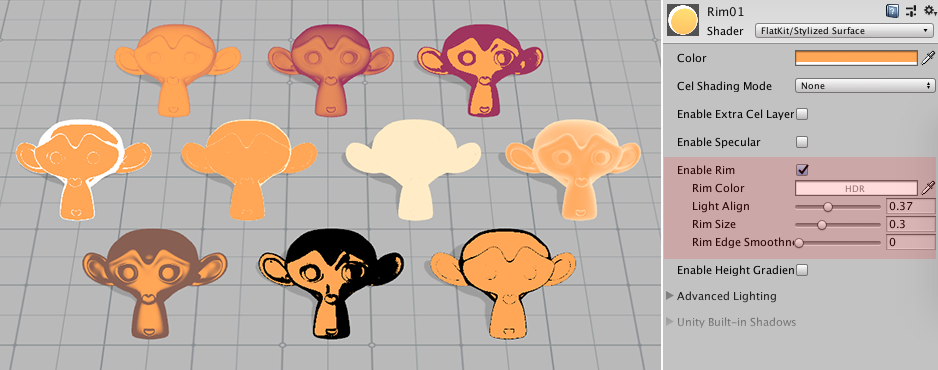
Variety of uses of Rim parameter alone on Suzanne the Blender Monkey. Interface of Stylized Surface shader with ‘None’ cel shading mode
Although Rim option is creatively useful and sometimes can remind an outline effect, there are two more obvious ways to add an outline using Flat Kit: to use Stylized Surface with Outline shader and/or to use Outline Image Effect camera component in Built-In RP/Forward Renderer’s Renderer Feature in URP. We’ll talk about both of them later in this manual.
TIP. Animate Cel layer size, Specular size or Rim size — to get a neat transition effect.
Height Gradient
This effect overlays a gradient (blend) from a selected opaque color to the transparency over an object. Height Gradient can be in world space or in local space.
TIP. As a reminder, another gradient-producing tool in Flat Kit is a Curve mode of Stylized Surface shader.
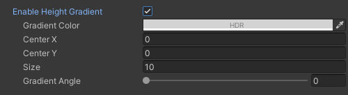
Height Gradient. Inspector interface
- Gradient Color picks the parameter’s own color to fade from into transparency. The parameter works in HDR.
- Space determines whether the gradient is in world or local space. The options are: World, Local. World Space means that the Center parameter is relative to the world origin, Local Space means that the Center parameter is relative to the object’s pivot point.
- Center X and Y are initial points from where the effect takes effect. Adjust these to move the gradient across the scene. Center X is useful if you engage - Gradient Angle, which means the rotation of the Gradient.
- Size determines how stretched the transition of Gradient is. The further the value is from 0 (zero) — the more gradual the effect is. Negative values flip the Gradient.
- Gradient Angle rotates the gradient.
A bit more about the nature and use of Height Gradient is covered in the Terrain Shader chapter.
Enable Vertex Colors
If enabled, the final shading of the object is multiplied by the vertex color values of the mesh. It is a debug parameter, usually it is not used for changing the look.
Outline
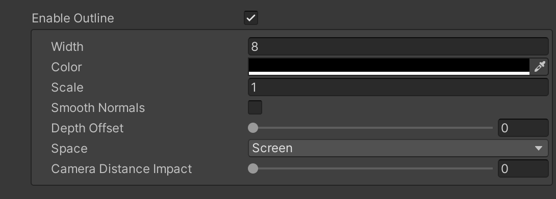
Outline part of Stylized Surface shader. Inspector interface
The Outline part of the Stylized Surface shader allows you to add pseudo-outlines to your models.
- Enable Outline — turns the outline on and off. Once turned on, a dedicated Renderer Feature will be automatically added to the Renderer the scene is rendered in. Unchecking Enable Outline removes the Renderer Feature. More info — a bit below.
- Select Renderer Feature — locates and selects the Renderer the object-based Outline is used in as a Renderer Feature. More info — a bit below.
- Width determines how thick the outline is.
- Color picks up the color of the outline.
- Scale adjust this parameter when you have gaps on the vertices. Please note, this is not an ultimate solution, the gaps need a complex approach — in modelling, adjusting the normals, adjusting camera distance etc. More info about the gaps issue can be found a bit below.
- Smooth Normals softens the normals of the model. This is useful when you have gaps on the vertices.
- Depth Offset moves the outline inwards or outwards an object. This is useful in cases when there are chatotic outlines on the model — pushing them behind the model can clean up the look.
- Space determines the space in which the outline is rendered. The options are: Object, Screen.
- Camera Distance Impact (this parameter is available in Universal RP only) if Space is set to Screen, this parameter appears. It makes outlines that are further from camera appear thinner than outlines closer to the camera.
Please remember that in addition to this shader Flat Kit has also a global Outline image effect applied per Renderer (in URP) and per camera (in Built-In RP). In the Outline Image Effect chapter in this manual you can find some useful specific and general info.
Flat Kit Per Object Outline Renderer Feature
Once you enable the Outline chaeckbox on the Stylized Surface material, a new Renderer Feature will be added to the Renderer. This feature is called Flat Kit Per Object Outline. You don’t need to add this Renderer feature manually, it is added automatically when you enable the Outline checkbox on the material.
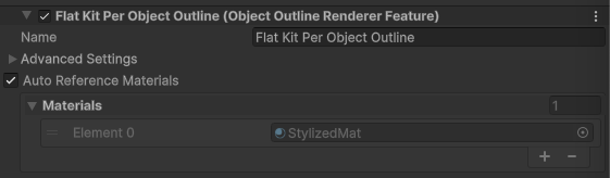
Flat Kit Per Object Outline Renderer Feature, main parameters
- Name — Render pass name. It is used to identify the pass in the frame debugger.
- Auto Reference Materials — Keep track of materials using outlines and automatically delete this feature if no materials use it. If disabled, you must manually remove this feature when no materials use it.
- Materials — Materials using this feature. The list is updated automatically based on the Enable Outline toggle on materials using the Stylized Surface shader.
Clicking the Advanced Settings line will reveal more parameters such as:
- Event — Choose at which point this render pass is executed in the frame.
- Filters — Settings that control which objects should be rendered.
- Overrides — Different parts of the rendering that you can choose to override.
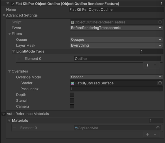
Flat Kit Per Object Outline Renderer Feature, main parameters
Auto-Reference Materials Warning
The per-object Outline works by adding a Flat Kit Per Object Outline Renderer Feature to your project’s URP Renderer asset. This happens automatically when you enable the Outline toggle on a material.
However, disabling the Outline toggle on the material does not always automatically remove this Renderer Feature. While our Auto-Reference Materials option attempts to clean this up for you in simple cases, it is not possible to reliably track all uses in complex scenarios or at runtime, thus the feature may be left active on the Renderer.
Therefore, we strongly recommend that when you decide to disable the outline on the material, you also manually check your Renderer and disable/remove the Flat Kit Per Object Outline feature from its list to ensure it does not use resources or leaves the material optimized for batching.
Gaps in the outline
The gaps issue appears in the shader-based (inverted hull) outline mostly on the sharp edges of the model. The most succeptible to this issue are the cube-like models and low-poly models.
In some cases it may be useful to manipulate the normals of your model in order to force the shader to render outlines where it wouldn’t do so otherwise.
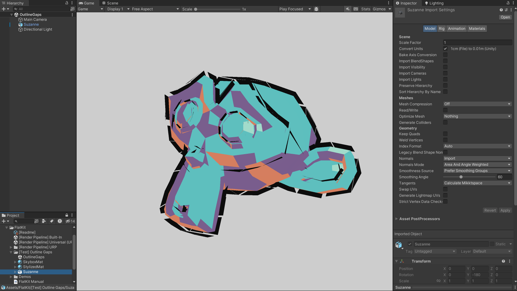
Gaps are visible on hard edges
There’s more information about using normals for outlines is in the Outline Image Effect chapter.
So, here are two easy ways to get rid of the outline gaps:
- Method #1 Select a mesh in the scene that carries the Stylized Surface material with the Outline parameter turned on. Then turn on the Smooth Normals parameter in the Inspector panel.
This toggle will run our custom algorithm to smooth the normals of the mesh. Please make sure to back up your model before using this feature, as it may change the appearance of the model. If you have a very complex model with a lot of sharp edges, you may need to adjust the normals manually in your 3D modeling software.
If the Smooth Normals parameter had already been turned on without the mesh being selected, you’ll need to turn it off and then on again, while the mesh is selected. This is because the mesh needs processing, not the material, in order for the Smooth Normals parameter to work.
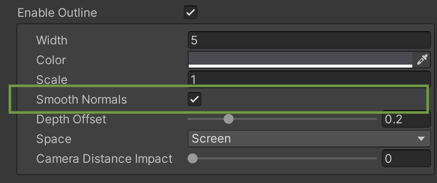
Smooth Normals in the Outline section of Stylized Surface shader
- Method #2 In the Import Settings of the mesh find the Normals parameter and change it from Import to Calculate. Then, drag the Smoothing Angle slider to the right. By doing so, you make the mesh smooth instead of sharp. The more you move this control to the right the bigger angle Unity will expect to consider it as sharp. Click Apply. The gaps should be gone or at least reduced.
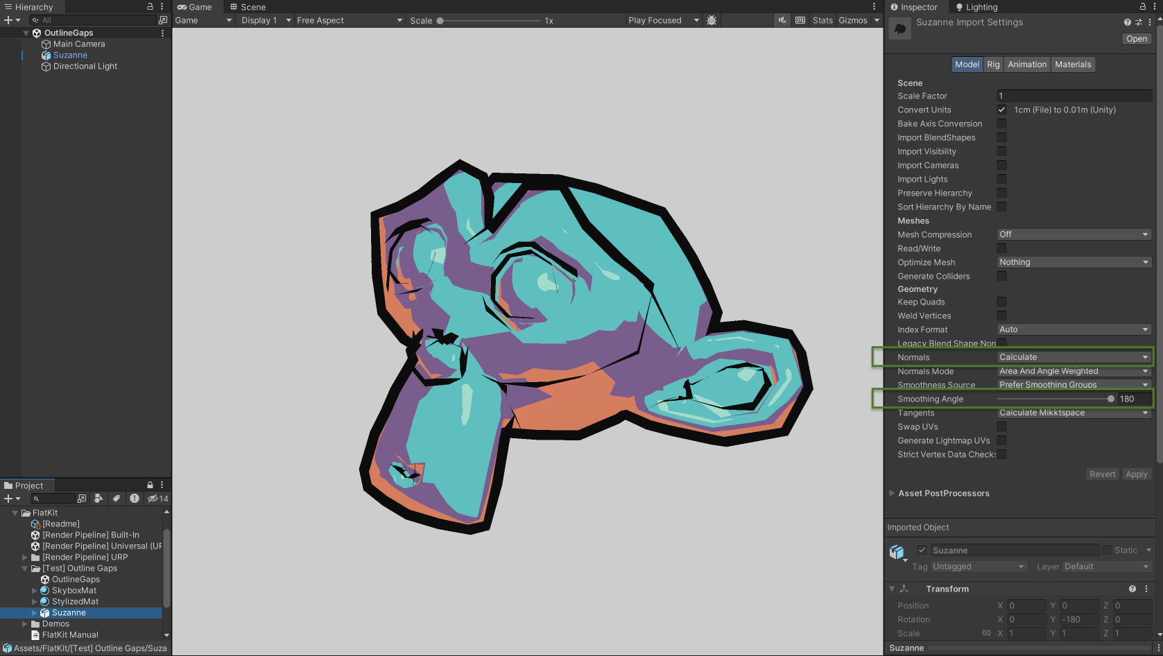
No gaps, Stylized Surface Outline on mesh with smoothened normals
As an extra step, to clean up the result a bit, you go to the material and increase Depth Offset a bit. This will ‘push’ the outlines away from the camera.
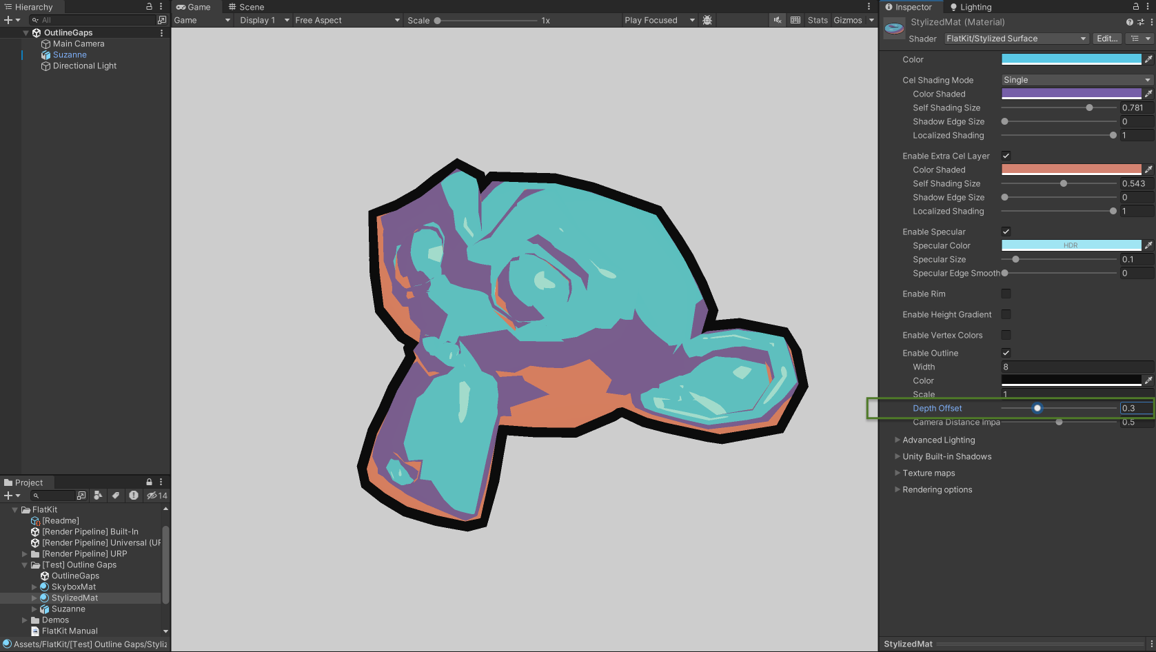
Using the Depth Offset parameter on the Stylized Surface shader to clean up the result
Please note that this way of doing the outlines is made to be super fast, but unlike in Photoshop it can’t produce an ideal outline. This method is called Inverted hull, when the vertices of a model are moved along their normals in the image space. There are fundamental limitations to this fast approach of making the outline. For example, the outline itself in not a hollow contour — but rather the modified normals layered on the back of the original model. In most cases it can produce very good results with very fast performance, but the transparency on this model won’t work, as reducing the model’s opacity will reveal the filled pseudo-outline layer in the background.
Also, to remedy the gaps issue, you can try using the Scale parameter of the Outline parameter. By keeping the Width low and increasing the Scale you can get rid of the gaps. But this is not a perfect solution, as it may make the outline look a bit displaced.
Additional Parameters of the Shader
Advanced Lighting
Light Color Contribution. Light Color Contribution defines how much the color of the light source of the scene impacts the color of the object. The value of 0.0 results in completely ignoring scene lights, the value of 1.0 results in full multiplication between scene light color and the object color. As an example, imagine the winter morning light. Usually it is blue-tinted, thus all the snow around can’t be white but rather blueish.
Please note that the effect is visible only if the color of the light is anything but white.
Light Color Contribution works only with directional light. The point and spot lights are contributing to colors and shading of the material regardless of the Light Color Contribution value.
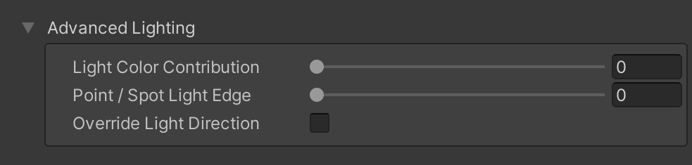
Light Color Contribution parameter on Flat Kit shaders Inspector panel
Let’s view it in example. Three pictures below describe how we change Light Color Contribution values on all (two) used materials: on a sphere and on a plane. Within a picture we change the intensity value of Directional Light as our main source of light. Additionally, there is a point light on each picture. This way it’s visible how local lights work together with the main Directional Light. Take the first image (below). At first, we turn down the Intensity to the very low value. White sun now has no impact on the scene brightness, resulting in a darker scene. Then we change the color of Directional Light from white to red. It has no effect because Directional Light is too “weak” to fill the scene. After raising Intensity value back to “1” the scene is now lighter and has a red tint.
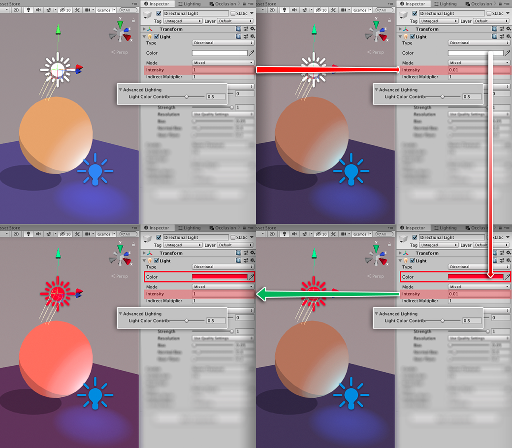
Light Color Contribution at value 0.5. Changing Intensity value and color of Directional Light
Once we change Color Light Contribution parameter to “0” (pic below), Directional light has no effect light-wise and color-wise. Changing Intensity parameter of Directional Light on the Inspector panel has no effect. Both sides of the picture are identical. This way you can achieve a flat look, in other words, the colors on the scene are exactly the same as you choose in the shader parameters.
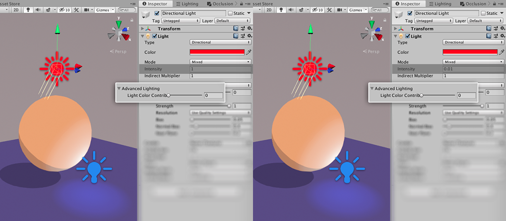
Light Color Contribution at value 0. Directional Light Intensity at max and min values
Now, (on the pic below) we raise Light Color Contribution to the max value of “1”. If we set Directional Light Intensity parameter low, the scene theoretically has no source of direct light. Local lights now act as the only light sources. If the Intensity of Directional Light is at its maximum, it’s too hot now.
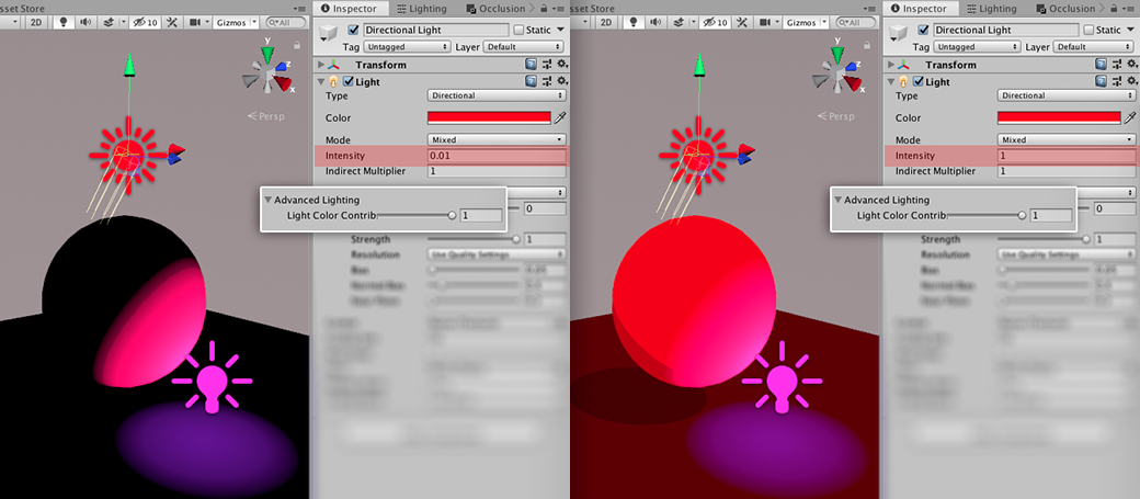
Light Color Contribution at value 1. Changing Intensity value of Directional Light
If you use a Particle System and choose your particles to emit light, Flat Kit shaders respect that!
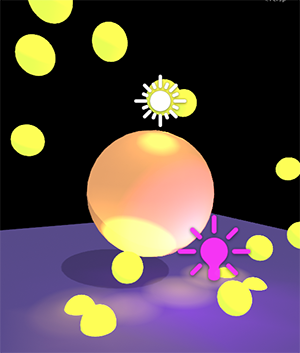
Particles emitting light on Flat Kit shaders
Override light direction It is a way to make the material have an independent direction of the light from the Directional Light. This can be useful in cases when you need to align the position of the cels or Rim or Specular. Normally, to adjust these parameters globally, you should rotate the Directional light. Once Override light direction parameter is enabled, the material no longer obeys the Directional Light, it now has independent mapping vectors for the light-dependent parameters (e.g. mentioned earlier cels, Rim, Specular) that you can adjust with Pitch and Yaw parameters. Simply put, you can rotate the the cels, Rim and Specular.
Unity Built-in Shadows
If the object has the ‘Receive Shadows’ option turned on in Mesh Renderer, you have an ability to use Unity-processed shadows on it, as you would do in Unity Standard Material shader, with a few extra-options.
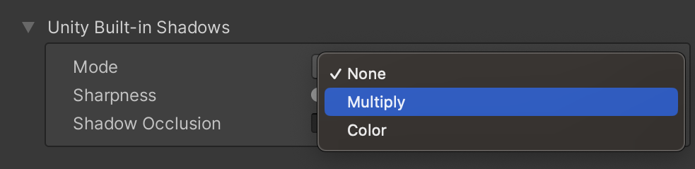
Unity Built-in Shadows mode menu. Inspector interface
- Mode lets you choose the coloring and blending parameters for the built-in shadows.
- None mode turns the built-in shadow parameter off.
- Multiply mode lets you cast the shadows as in default material. You don’t have direct control over the color. You can change intensity and sharpness. The blending mode is ‘Multiply’.
- Color mode lets you choose the color of the cast shadow. The blending mode is ‘Normal’. The opacity of the shadow is controlled by the alpha parameter in the color chooser.
- Sharpness defines how blurred or crisp the shadow edge is.
- Shadow Occlusion masks received Unity shadows in areas where normals face away from the light. Useful to remove shadows that ‘go through’ objects.
NOTE. Shadow Occlusion parameter is available in the URP version of Flat Kit only.
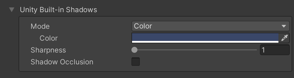
Unity Built-in Shadows in Color mode. Inspector interface
Texture Maps
If you’ve got a UV-unwrapped mesh, you can add a set of textures to it. The shader supports Albedo, Detail, Normal and Emission maps.
If you work with transparency in textures in Built-In RP, please use Stylized Shader Cutout shader. It can use alpha on the texture as transparency. URP supports alpha by default.
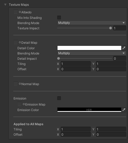
A set of textures in Stylized Surface shader
Albedo Allows to use the albedo, or diffuse texture. In URP this slot supports transparent textures by default. Can be used together with Alpha Clipping parameter (explained below).
- Texture selection slot lets you pick a texture;
- Blending Mode lets you choose between ‘Multiply’ or ‘Add’ blending modes. ‘Multiply’ Blending Mode multiplies the luminosity of the base color by the blend color. Multiplication by white produces no change, while the black pixels remain, making the material darker. ‘Add’ Blending Mode is a little bit different from ‘Multiply’ — blending with black color produces no change, while generally it brightens the bright colors.
- Texture Impact controls how visible the texture is. Values to the left decrease visibility of the texture up until it is invisible.
TIP. If you would like to have a material with a texture with a cel shading on top of this texture, you can set the Stylized Surface to Single Cel Shading Mode, set the base Color to white or light grey, set the Color Shaded parameter to a bit darker one, set the Albedo texture (if your texture is not mostly white) to Multiply Blending mode, Texture Impact to the maximum value. You should get the model filled with a texture and with cel shadows combined.
Detail Allows to use a second albedo texture. It is blended with the first one. The blending modes are: Multiply, Add, Interpolate.
- Texture selection slot lets you pick a texture;
- Detail Color picks the color of the second texture;
- Blending Mode lets you choose between ‘Multiply’, ‘Add’ or ‘Interpolate’ blending modes;
- Detail Impact controls how visible the second texture is. Values to the left decrease visibility of the texture up until it is invisible.
NOTE. Detail map support is available in Universal RP version of Flat Kit only, there is no Detail map parameter in Built-In version of Flat Kit.
Normal Map To make an impression of a relatively low-poly mesh having many details of a high-poly one, you can use normal maps. Add one to Normal Map slot in the Inspector panel.
- Texture selection slot lets you pick a texture;
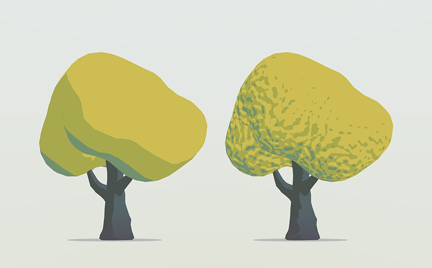
Normal Map Tree Demo scene, a tree without and with a normal map
Emission Enables Emission map part of the shader.
NOTE. Emission map support is available in Universal RP version of Flat Kit only, there is no Emission map parameter in Built-In version of Flat Kit.
Emission Map Allows to use custom emission maps to designate the parts of the meshes to have a ‘glow’ effect.
- Texture selection slot lets you pick a texture;
- Emission Color chooses the color of the ‘glowing’ effect.
The tiling and offset parameters apply for all the textures simultaneously.
- Tiling repeats the texture along X and Y axis;
- Offset shifts the texture along X and Y axis within the UV map of the mesh;
Rendering options
This section is available in the Universal RP of Unity. Built-In RP doesn’t have alpha clipping on the shader level, so you can use the Stylized Shader Cutout shader instead.
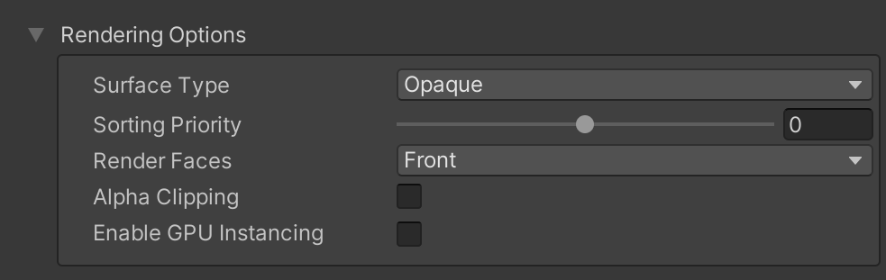
Rendering options part of the Stylized Surface interface
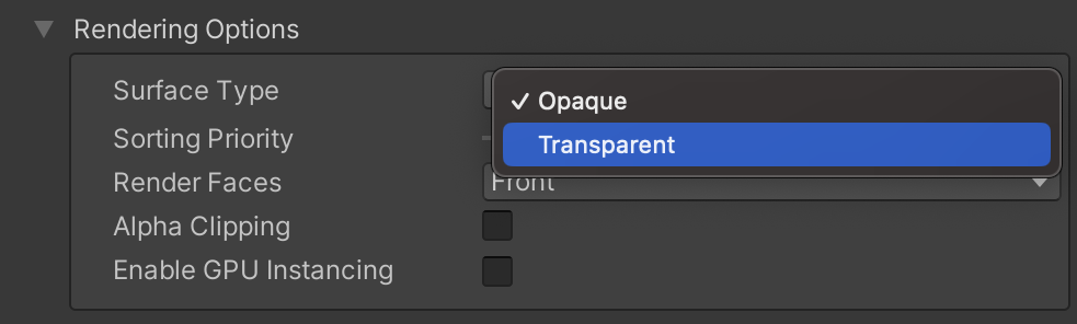
- Surface Type — The two options are Opaque and Transparent.
- Blend Mode — If Transparent Surface Type is selected, the Blend Mode menu becomes available with the following Blend Mode options: Alpha, Premultiply, Additive and Multiply.
- Sorting Priority — determines the chronological order of rendering for the Material. Materials with lower value are rendered first.
- Render Faces — lets you choose between Front, Back or Both faces of the mesh to be rendered.
- Alpha Clipping — Discards pixels based on the Albedo texture’s alpha channel. If enabled, the Threshold parameter appears.
- Threshold — The minimum alpha in the Albedo texture to render a pixel, i.e. determines how soon the transparent portion is ‘transparent enough’ to be cut out.
- Enable GPU Instancing — Uses GPU Instancing to render multiple copies of the mesh at once. More information in Unity’s documentation and in this doc here.
Setting material values from scripts
The following are the color field names for manipulation via the code for tweening, randomization etc:
_BaseColor(in URP),_Color(in Built-in RP): the primary color, “Color” in the inspector. The alpha value controls transparency of the object ifSurface Typeis set toTransparent_ColorDim(and_ColorDimSteps,_ColorDimCurvein the corresponding cel shading modes): Color Shaded in the Inspector_ColorDimExtra: the shaded color of the “Extra Cel Layer” feature_FlatRimColor: rim color, requires “Enable Rim Color”_FlatSpecularColor: specular color, requires “Enable Specular Color”_ColorGradient: the gradient color used along with the_BaseColorparameter when “Enable Height Color” feature is active- The full list of parameters is at the top of the file
Assets/FlatKit/Shaders/StylizedSurface/StylizedSurface.shader.
NOTE. The outline toggle is implemented as a shader keyword, so unfortunately it can’t be toggled at runtime. However, you can enable the outline in the material inspector and toggle its visibility in code by setting the outline width (0 will visually disable the outline). Or, you can create two identical materials with the only difference being the outline toggle, and switch between these materials at runtime with renderer.material = myMaterial.
Stylized Surface Cutout Shader
NOTE: ‘Stylized Surface Cutout’ shader has been deprecated in Flat Kit 2.1.2 for Universal RP version (‘Stylized Surface Cutout’ is still available in Built-In RP version). Because URP supports transparency by default, there’s no need for this separate shader in URP.
The Stylized Surface and Stylized Surface with Outline shaders can do everything Stylized Surface Cutout could — using Rendering options part of the shaders in the bottom of the interface. There you can find an option to set the shading in transparency mode (Surface Type drop down menu ▶︎ Transparent. The default type is Opaque).
This is a version of Stylized Surface shader with an option to treat alpha as transparency on a texture. The rest of the shader is the same.
The Base Alpha cutout parameter determines how much of the alpha portion of the texture is going to be transparent.
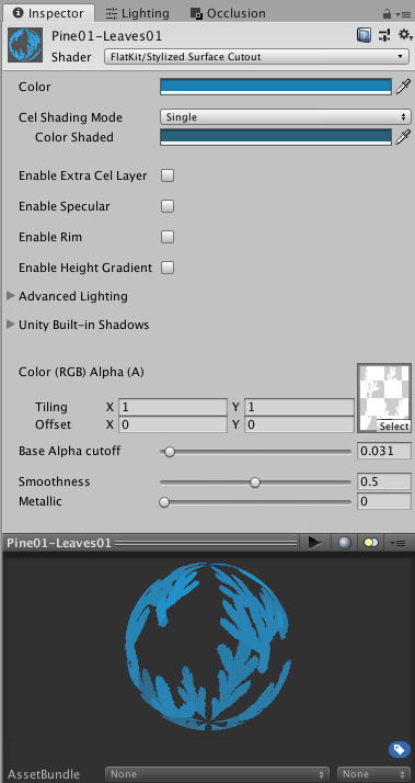
‘Stylized Surface Cutout’ shader — Valley demo scene, tree branches material. Inspector interface
Use this shader if you work with transparency in Built-In RP. In URP you are good to go with the Stylized Surface shader instead of this one. It will spare a few cycles from your CPU.
Stylized Surface with Outline Shader
NOTE: Stylized Surface with Outline shader has been deprecated in Universal RP version of Flat Kit: the outline functionality has been moved to the Outline parameters of Stylized Surface shader. Stylized Surface with Outline remains available and working for the sake of compatibility with existing projects, but it is advised to use Stylized Surface for the new projects instead. Stylized Surface with Outline has not been deprecated in Built-In LTS version of Flat Kit.
You can use Stylized Surface shader to outline a particular object. It is a parameter (shader pass) that is built on top of the Stylized Surface shader. It has all the features of the Stylized Surface shader plus the outline feature.
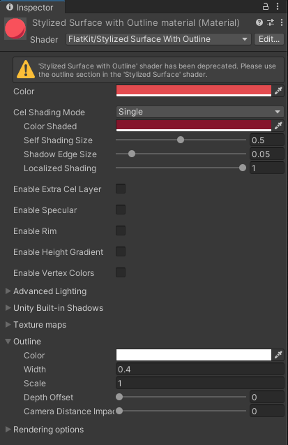
‘Stylized Surface with Outline’ shader
- Color picks up the color of the outline.
- Width determines how thick the outline is.
- Scale adjust this parameter when you have gaps on the vertices (please note, this is not an ultimate solution, the gaps need a complex approach — in modelling, adjusting the normals, adjusting camera distance etc. More about the gaps issue can be found a bit below).
- Depth Offset moves the outline inwards or outwards an object.
- Camera Distance Impact (this parameter is available in Universal RP only) makes outlines that are further from camera appear thinner than outlines closer to the camera.
GPU Instancing
When the Enable Instancing option is enabled on a material, the shaders can perform GPU Instancing of the following fields that are common across all Flat Kit shaders:
- Color value (property name
_Color), - Parameters of the cel shading mode “Single”
- Shaded Color value (property name
_ColorDim),
- Shaded Color value (property name
- Specular parameters, active when “Enable Specular” is checked
- Specular Color value (property name
_FlatSpecularColor), - Specular Size value (property name
_FlatSpecularSize), - Edge Smoothness value (property name
_FlatSpecularEdgeSmoothness),
- Specular Color value (property name
- Rim light parameters, active when “Enable Rim” is checked
- Rim color value (property name
_FlatRimColor), - Rim size value (property name
_FlatRimSize), - Edge Smoothness value (property name
_FlatRimEdgeSmoothness), - Light Align value (property name
_FlatRimLightAlign),
- Rim color value (property name
- Unity shadow parameters, located in the “Unity Built-in Shadows” section
- Color value (property name
_UnityShadowColor).
- Color value (property name
Using DOTS
To enable DOTS in Flat Kit, please locate the StylizedSurface shader file, open it in a text editor and uncomment the line #define FLAT_KIT_DOTS_INSTANCING_ON.
Dissolve Effect
This kind of dissolving effect can be done in any shader that supports the texture, its impact control and the threshold for the cutout of the transparent pixels in a texture.
Below is an example of how we’d do this effect in the Stylized Surface shader.
- Add a noise texture to the material. Insert it to the Albedo (diffuse) slot and set the Impact to 0 if needed. The texture should not necessarily be a noise one but it should have transparent areas in the alpha channel.
- Set the Alpha Clipping parameter to On in the Rendering options section of the shader.
- Adjust the Threshold parameter to make the effect kick in. At 0, the texture is fully visible, at 1, it is fully cut out.
In the Room Demo scene the dissolve effect was applied to the plant material. If you launch the scene (press Play), you can see the plant dissolve. The noise texture can be found in Common ▶ Textures ▶ Misc ▶ Dissolve.
Comments